Vintage Tools
Of Course! We use vintage tools to fix all our other vintage stuff...
The following links will direct you to topics discussed on this page:
We've got two kinds of tools here:
- Shop Tools (wrenches, drills, etc)
- Office Tools (staplers, check writers, etc)
In addition to this, we have a Calendar of Swing Dancing in DC, a Directory of Vintage Clothing Stores and a Guide to 1940s Collectibles. Thanks for tuning in! Feel free to Contact Me if you have questions or want to share photographs and "tool talk" with the rest of the readers.
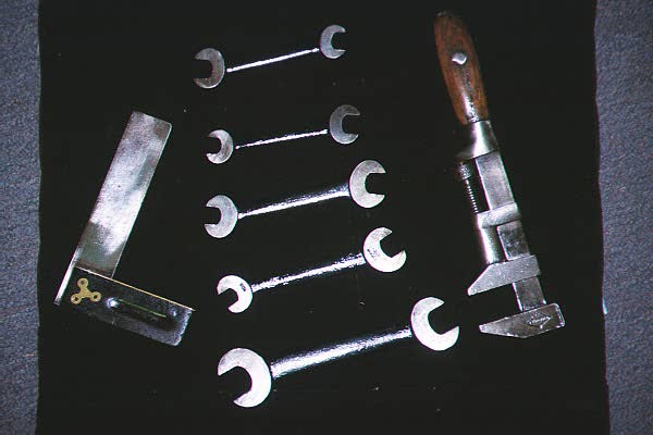
Vintage Spanners
and other lovely objects
Click to Enlarge
I found the set of spanners shown here at an estate sale in Arlington. The lady wanted about a quarter for each one. They were heavily rusted, so I had to rely on a tool catalogue for the appropriate restoration. If you look VERY closely at the very beginning of the film "My Dog Skip", there is a scene where the character "Dink Jenkins" is working on his car --- you will note that an identical set of spanners is being used. Here's a design patent for spanners from 1938:
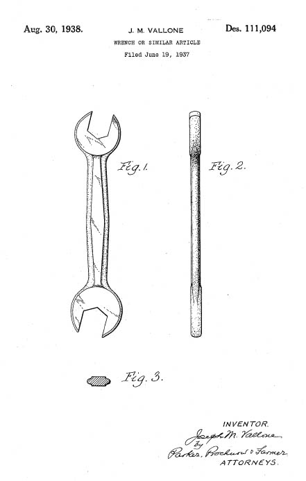
Spanner Design Patent
Joseph Vallone, Patent D-111,094
Click to Enlarge
Click Here if you want to learn how to get free patent drawings
In the same lot, I was privileged to find a rosewood square (top) and a glorious Stilson Wrench. The latter is a real art object.
Click here to look at another type of collectible, or keep on scrolling for more Tools.
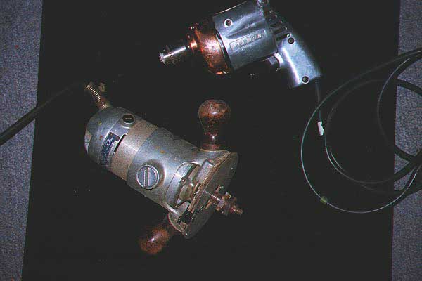
Router and Drill
Early Power Tools
Click to Enlarge
This is a Remington electric drill from the late 1940s. This is a gorgeous piece of copper and chrome that was made to last a lifetime. It still works like a charm --- anad all I had to do was clean it up.
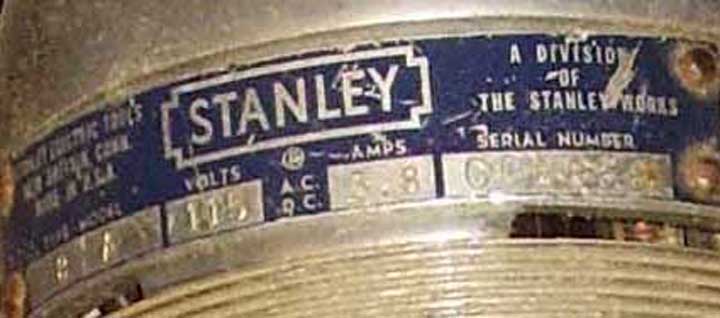
The Router is a very early Stanley model -- it is a Type 8 Model A probably from around 1951. It has NONE of the consumer amenities of today's routers. On the other hand it has a whole lot of power. Here are some closeups of the Router:
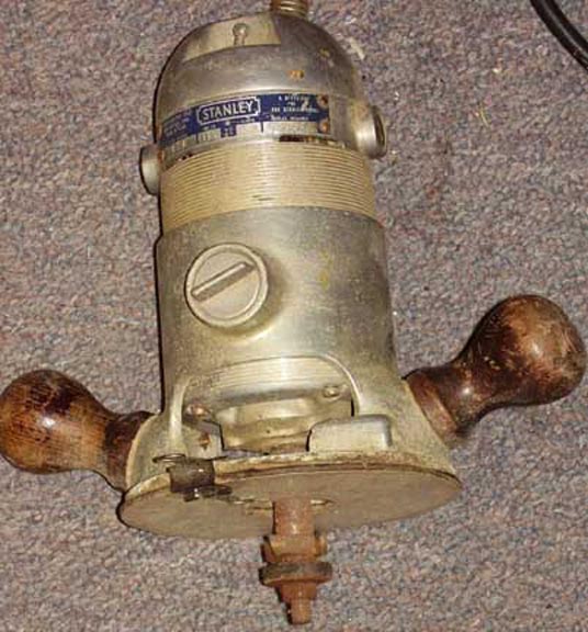
Stanley Router - My Dad Used this as a Veneer Trimmer
The Stanley Router (Serial number CC8858)
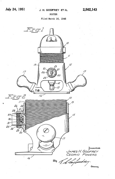
Mr. Godfrey and Mr. Powers Patented the Router on July 24, 1951
Click to Enlarge Click Here if you want to learn how to get free patent drawings
We just got this note from our Reader, Ian in Kansas:
"... I was pleased to see some information about the age of the Stanley router - I have one of these that I acquired from my grandfather's shop when he passed away in 2002. It's still my primary router because none of the modern ones have the feel, balance, and sheer power of this unit. It's a perfect router for freehanding, and I wouldn't trade it for anything. Glad to find out how old it really is. ...
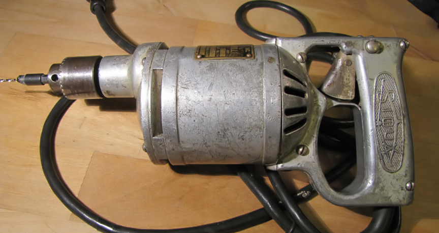
Below is a photo of a very old power drill that was sent in by our reader Randy. It has a metal information plate with the following information:
Albertson & Co.
Sioux - trade mark
Sioux City, Iowa
Randy writes:
"... The drill still works. I'm trying to find out more about this drill and it age. I looked up the company in google and others but the company seems to have dissappeared (probably bought out) in the late 1920's. The drill has the "SIOUX" trademark so I'm sure it was produced before the company dissappeared...According to the company history from an industry listing from 1922 in Sioux City Iowa, this company was once one of the largest 'valve grinding' companies in the world... "

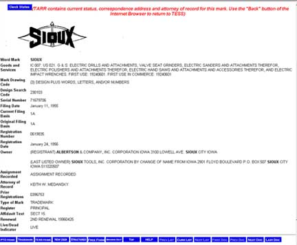
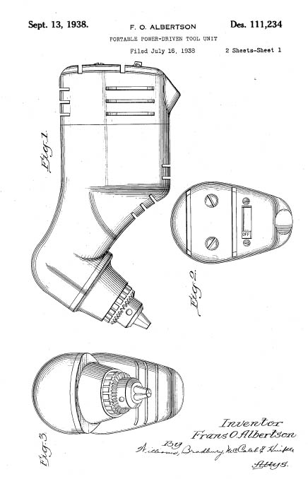
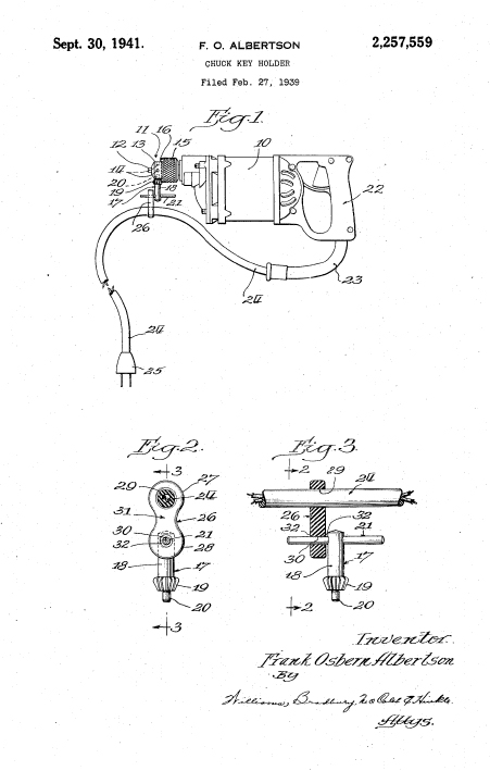
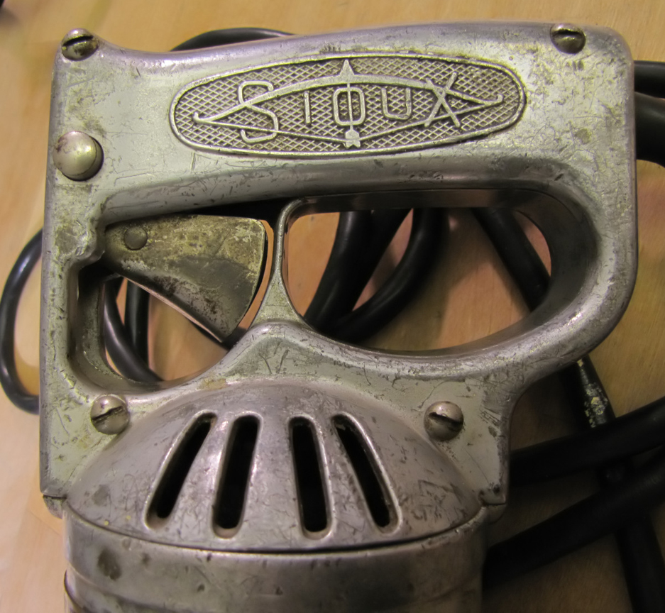
The Sioux Drill, Trademark, and Patent
In Use Since 1924
F.O. Albertson Patent D-111,234
The "Trigger" is Very Unusual
Click to Enlarge
Click Here if you want to learn how to get free patent drawings
We got this note from Christina, one of our readers
"The particular drill in question is from the 1940's it was used, and probably designed for production line work, notably the aviation war effort. The same drill continued in production unchanged into the eighties, albeit, still marketed to industrial applications rather than domestic use. Today the same drill design ( plastic casing, of course) still bears the company's name and has been brought to the domestic stage under MILWAUKEE brand. Sioux focuses mostly on the air tools market as they have since the fifties nowadays. Check out: SIOUXTOOLS.COM"
Our reader Karl added even more clarification:
"... As I recall, Milwaukee has produced their "Close Quarters Drill" for some time, which was based upon, and licensed by Sioux, though Sioux primarily produced pneumatic tools. However, Milwaukee does not own Sioux Tool, nor is Sioux gone altogether. Snap-On bought Sioux Tools in 1994, and moved them from Iowa to Murphy, NC, in 2001. The whole history is here. I own a old Sioux compact screwdriver myself, and figure that it will continue to run well after I am gone. Though they now do sell electric-powered tools, it seems the air-drives tools continue to be their main focus. ..."
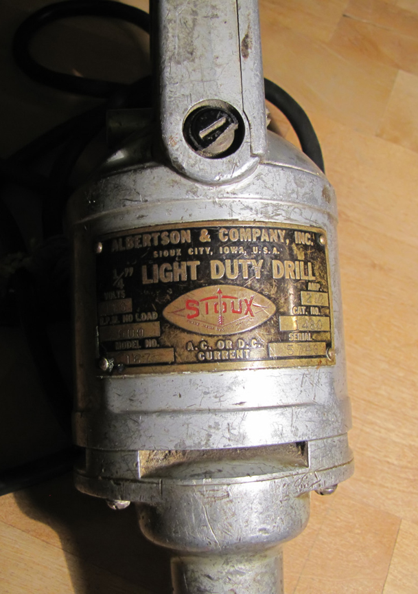
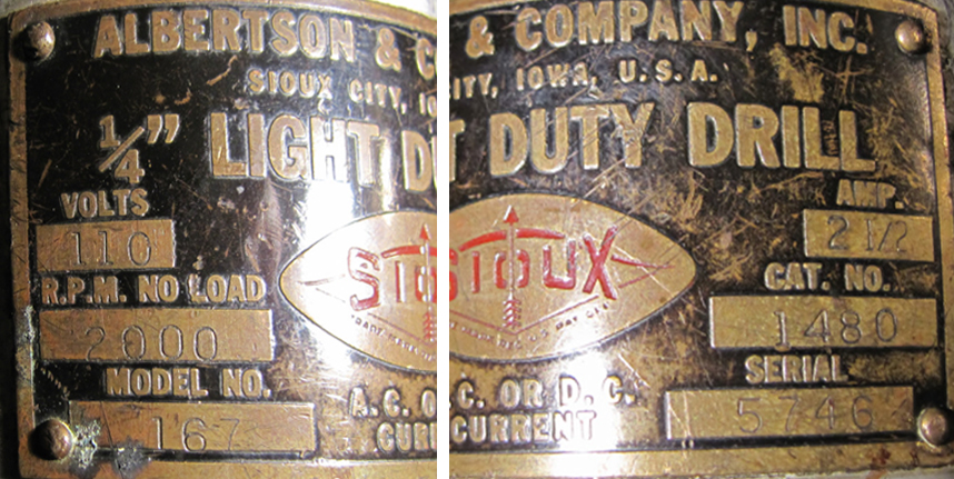
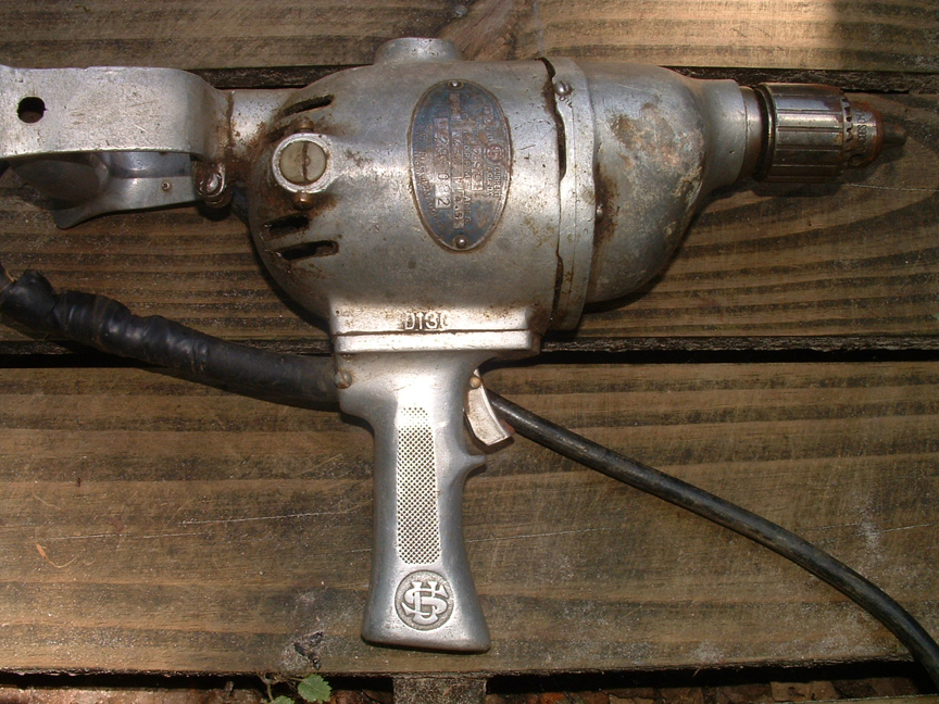
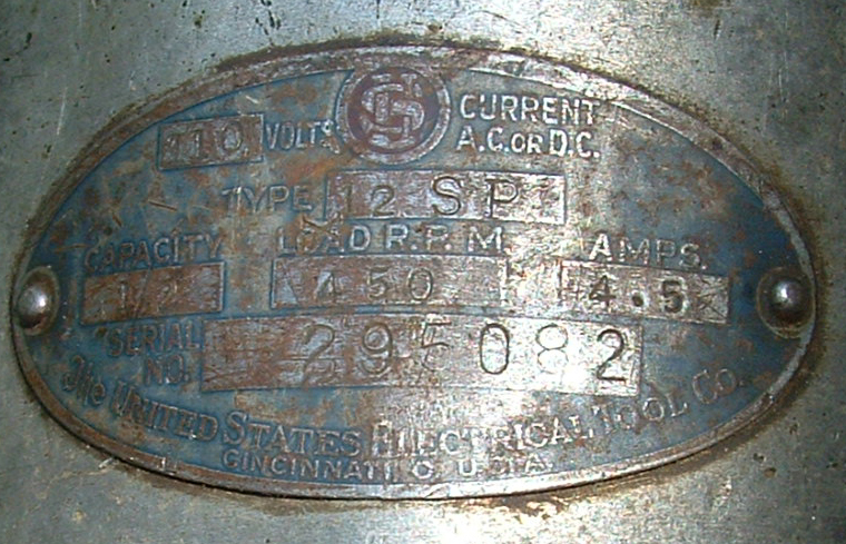
Here is another fairly old Sioux drill, sent in by our reader Frank. He writes:"... I got this at an estate sale. It was sitting with a pile of trash on the side of the house. I gave the lady $5 for it; it weighs a ton but works like a champ. All I had to do was clean 50 years worth of grease and grime off of it. I love the smell of grease in the morning-it smells like.....victory. (The serial number reads 12180)...."
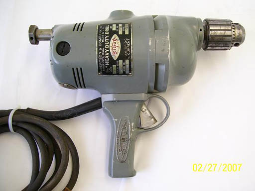
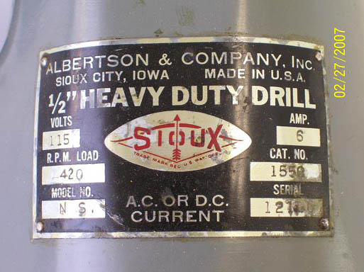
Frank's Sioux Drill and he Manufacturer's Plate
It must be fairly old, since it can use AC or DC current!
Click to Enlarge
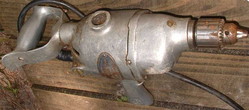
Here is a drill that bears the Albertson name. It was sent to us by our reader John who writes:
"... I was searching for information on the (attached photo) Albertson drill. This was my father's, and I remember him using it all through my childhood. I got it after he passed away, and still use it to this day. Is there any way to find out just how old this thing is? It is one amazing piece of work: very strong, very reliable. ..."
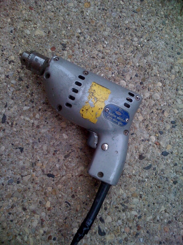

John's Dad's Albertson Drill
Based on the 1940 Patent, it looks like the drill came from the 1950s
Manufacture's Plate data sent in by John
Contact Us if you can date this drill
Click to Enlarge
Albertson also did pioneering work in making a polishing device. These patent diagrams from the 1930s show a polisher that could be on the shelves at a hardware store in 2009.
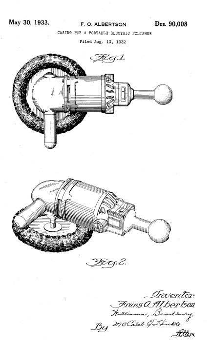
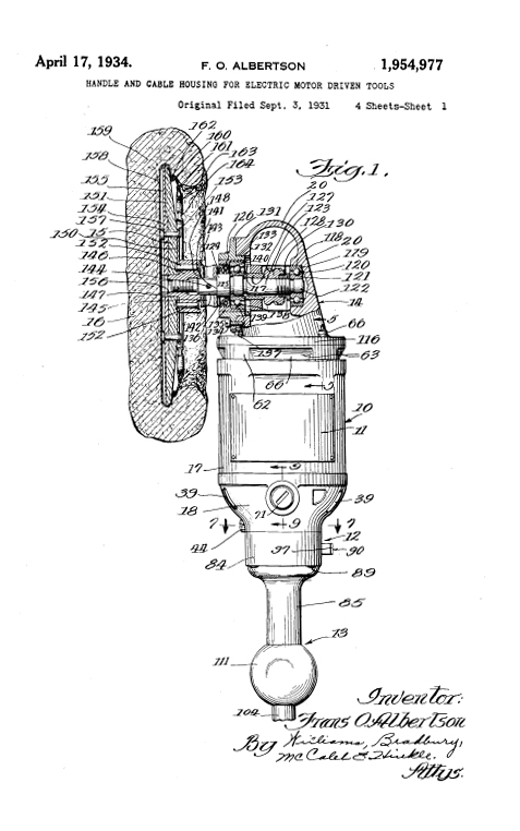
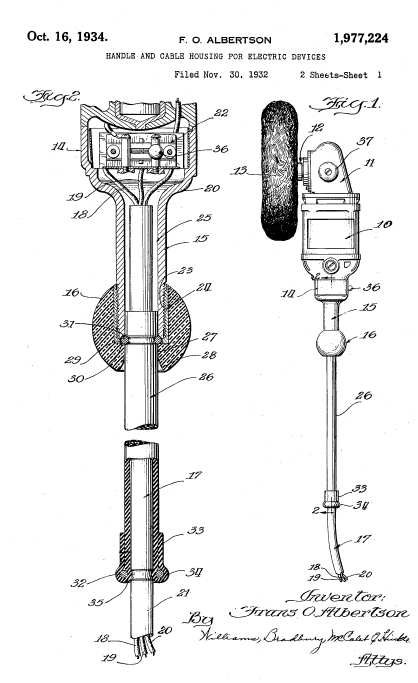
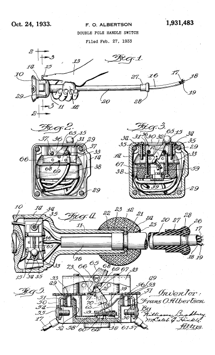
The Albertson Polisher
Design Patent D - 90,008
Mechanism Patents: 1,945,977; 1,977,224; and 1,931,483
Click to Enlarge
Click Here if you want to learn how to get free patent drawings
Our reader Norman had a positive experience with a Sioux tool. He would like some help, though:
"... was doing a search for Albertson & Co, the manufacturer of Sioux brand power tools and your site came up with some of their actual products. I recently bought a Sioux Flexible Shaft Grinder at a garage sale for $20. It worked for a couple hours, then the switch failed and I am attempting to locate a new switch. I have attached a photo of an add from 1946 from an ebay auction of the exact same piece of equipment I have, just so you will have a visual reference, while pondering any greatly appreciated suggestions. If you like, I would be happy to take and send you some photos of this unique and fantastic tool. It still works after I by-passed the switch but it is such a cool tool I want to give it the respect it deserves and find the correct switch for it. ..."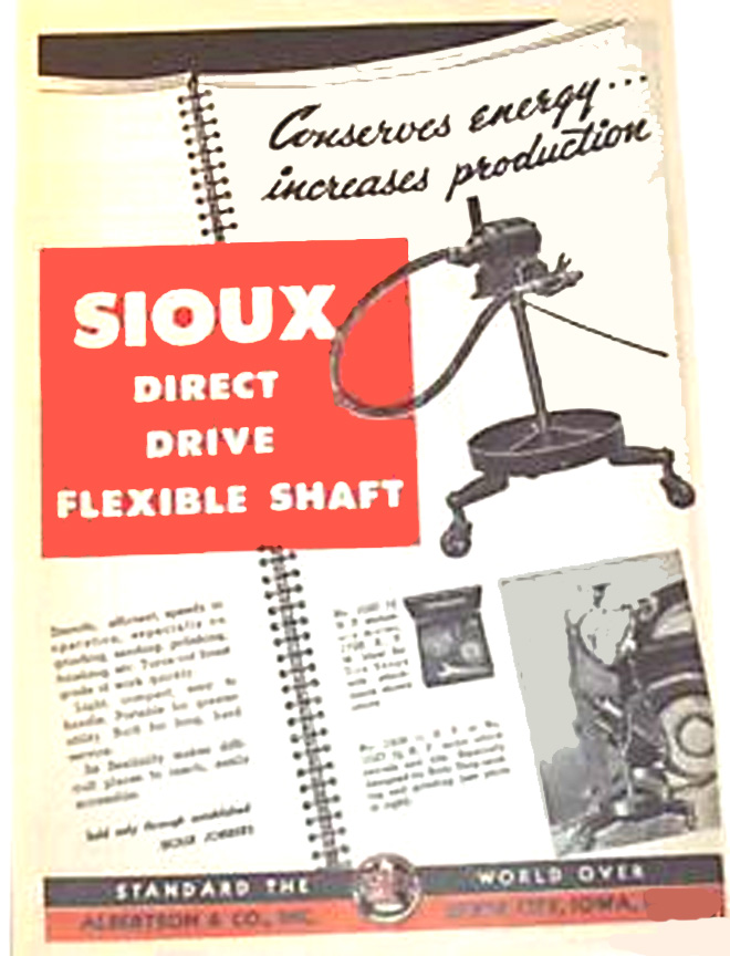
Norman's Flexible Shaft Grinder
Contact Us if you can suggest a replacement switch
Click to Enlarge
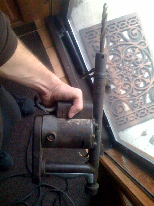
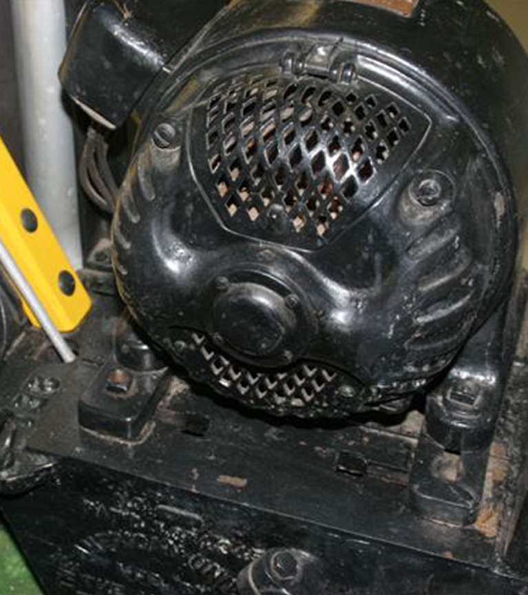
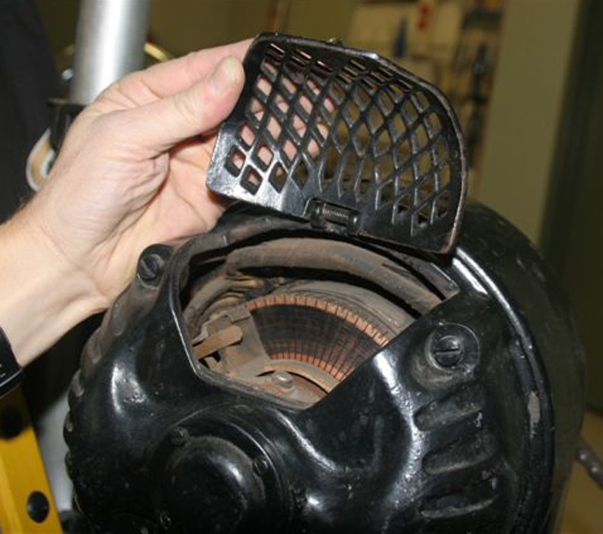
As a segue to our next section, we received this note and pictures from our reader Mark who writes:
"... Howdy! Just bought an old Sioux drill today at a yard sale, and have been trying to figure out how old it is; see attached photos. It's clearly a close sister to the Rural Craft drill (see below) you have on your website. Like the Rural Craft, it also takes either AC or DC, according to the nameplate. It's a beauty--I have already used it on a light carpentry project, and it works like a champ. If you or any of your readers have any info on the likely year of manufacture, I would very much like to know. ..."
Mark's Sioux Drill
Contact Us if you can date this drill
Click to Enlarge
Our reader Levi sent us thes photos of a Sioux tool cabinet that looks like it is in the same period as the drills featured on this page. Levi writes:
"... Snap-on bought out Sioux and their tech support told me that it is a #677 Valve Cabinet. It would have had the valve machine on top of it and the cabinet was used to store the accessories. Originally manufactured in the mid-1930's ..."
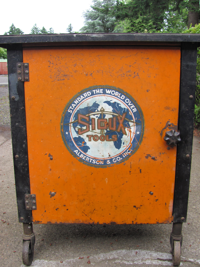
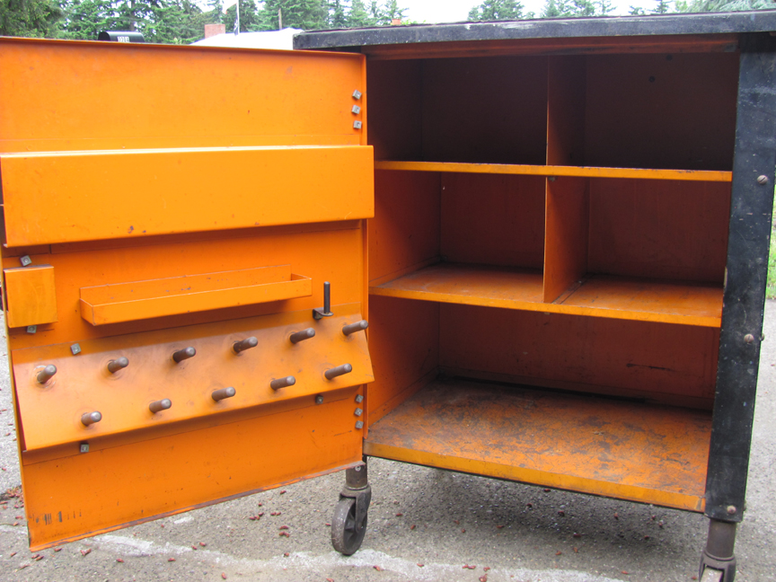
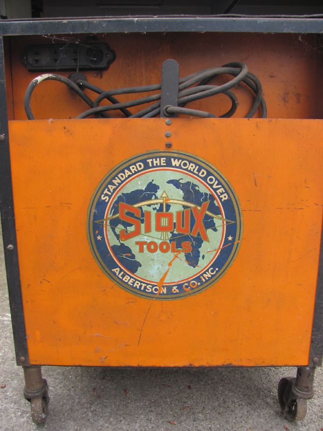
Levi's Sioux Rolling Cabinet
Click to Enlarge
"Rural Craft" is another brand name for Sioux. Here is a letter and photo sent to us by Wayne, one of our readers:
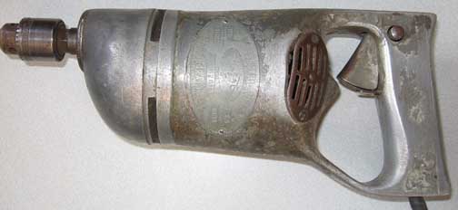
The Rural Craft Drill and Nameplate
Click to Enlarge
Wayne writes:
... I've come upon an electric drill that I can't seem to find any info on (google, yahoo, etc.) I've searched a few archives, and can find the company, but no mention of this as a product line. I've taken the liberty of attaching two images. Unfortunately, the name plate may be a bit difficult to read. Not a very good camera for macro. At least this is my story (probably age is getting to the eyes. Been squinting so hard, eyes are sharing the same socket!)
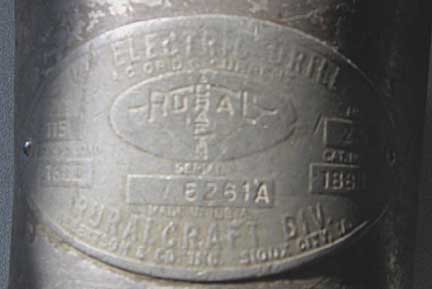
The nameplate reads:
RURAL CRAFT
115 Volts, R.P.M. no load 1600, Amp 2.5, Cat.No. 188D (or 1880?), Ser.No. 6261A
RuralCraft Div.
Albertson & Co. Inc.
Sioux City, IA.
Clearly, from the design patent above, Albertson and Sioux are synonymous.
We would love to hear more about this drill or other Sioux products.
Click here to look at another type of collectible, or keep on scrolling for more Tools.
We are very pleased to learn about the Phillips Impact Drill. Here is a letter and photo sent to us by Jeff, one of our readers:
The Phillips Impact Drill
Click to Enlarge
Jeff writes:
"... Came across your page online,and figured I'd give asking you a shot.I found this drill at a local sale recently and I can't find any information on it (year it was produced, info on the company, etc.) I researched the patents found on the end of the power cable (US PAT 1565321, 1611014, 1918070) and found out that W.A. Frantz was the inventor of the power plug design in 1923... This is Type 94-D and operates on 110 volts and draws 2.5 amps ..."
The nameplate reads:
MOTOR HAMMER
NO 2
CHICAGO, ILL USA
PAT APLD FOR
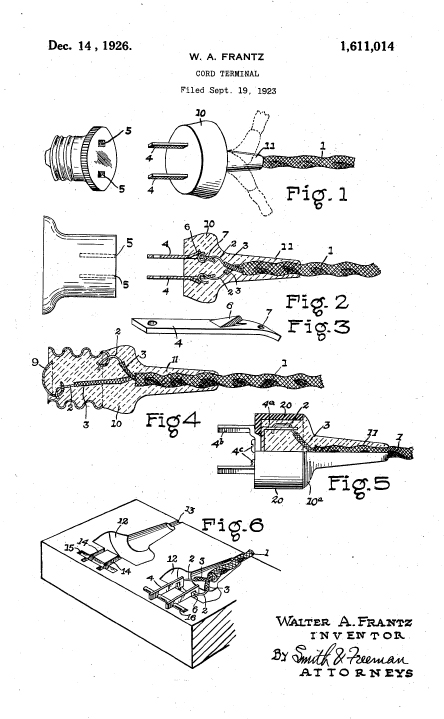
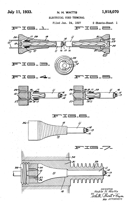
Jeff is indeed correct in noting that the patents referenced above are for the plug and the cord, and these (Frantz, Watts) date to the 1920s. The Phillips company applied for a patent on the drill in 1933 and it was granted in 1934. From this, we'd think that the drill was made sometime between 1933 and 1934.
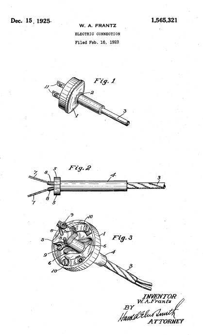
The Phillips Impact Drill
Frantz Electrical Plug Patent Nos. 1,565,321 and 1,611,014
Watts' Electrical Plug Patent No. 1,918,070
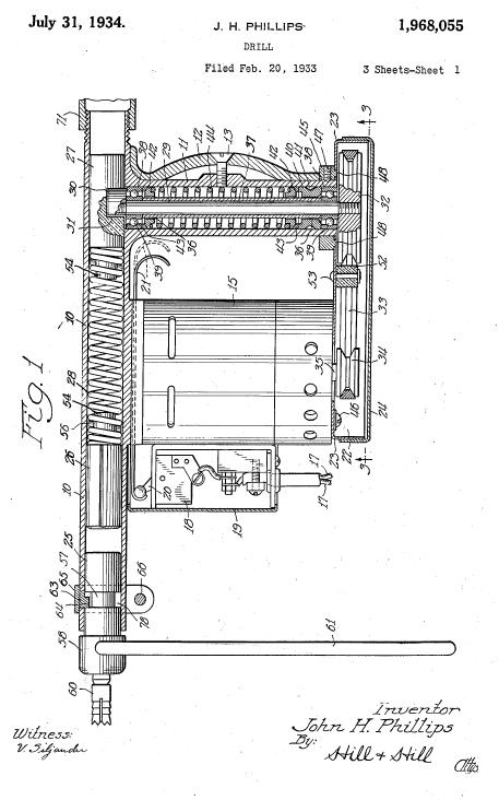
Phillips Impact Drill Patent No. 1,968,055
Click to Enlarge
Click Here if you want to learn how to get free patent drawings
Here's what Mr. Phillips has to say about his drill:
"... My invention relates to improvements in electrically actuated tools and has particular reference to a portable tool adapted for drilling vertical and upwardly inclined holes in concrete walls, ceilings, roofs, and the like. The invention contemplates the use of a belt drive rather than gears to connect the motor with the plunger actuating mechanism, thereby minimizing the vibratory shocks upon the windings of the motor which shorten its u^aful life when gears are utilized as a part of the actuating mechanism. The use of a belt drive also minimizes the no;ses usually incident to the operation of a motor actuated tool having gears as a part of the power transmission mechanism. A general object of the invention is the provision of a tool of the kind described which is compact, light in weight, economical to manufacture and has its essential movable parts such as plungers and connecting spring so arranged as to be quickly and easily removed for inspection, cleaning or repair without the use of tools or the necessity of dismantling the housing -in which such parts are mounted. ..."
We would love to hear more about this drill or other Phillips products.
Click here to look at another type of collectible, or keep on scrolling for more Tools.
FLOOR SANDER
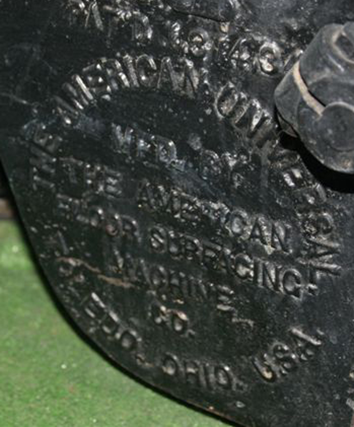
Here is a vintage floor sander made by the American Floor Surfacing Machine Company of Toledo, Ohio. This company, which was in business from at least 1909 through 1957, was known for their floor sanders. They also made a combination machine known as the "Electric Carpenter". They also made handheld power tools (sanders, circular saws, and chainsaws) and machines for surfacing concrete and terrazzo floors.
Here is an ad for the "Handy Sander" and a photo of the "pre-deco" version
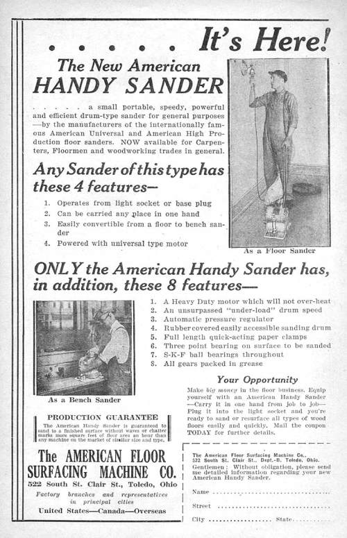
American Floor Surfacing Machine Company
The "Handy Sander Before Streamlining
Click to Enlarge
In 1938, the company gave the "Handy Sander" a new Streamlined look, as illustrated in these patent diagrams:
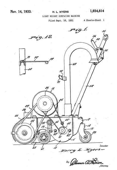
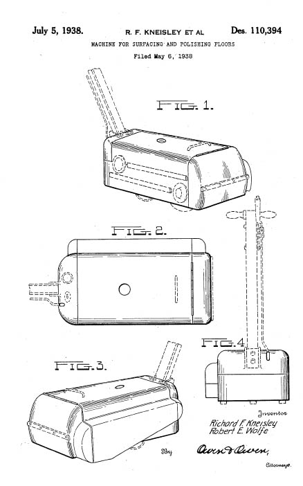
American Floor Surfacing Machine Company Patents
(Left) The "Handy Sander Before Streamlining (Patent No.1934814)
(Right)The Same Tool After Streamlining (Patent D-110,394)
Click to Enlarge
Click Here if you want to learn how to get free patent drawings
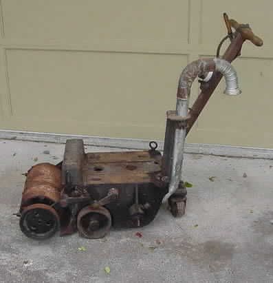
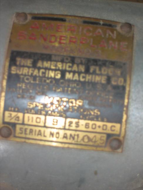
Here are some more photos of the American Floor Sander, sent by our reader Lloyd. He writes:
"...I checked the motor brushes and they must have been replaced just prior to the original owner retiring the machine. Here's what I can tell you about the machine:
The original owner was a professional floor sander, probably from the 20's to the fifties. He then bought or possibly founded Peg Rentals with proceeds from this machine and, I assume, either sold or gave the business to his son, John Sakiw. In 1986, just prior to selling the rental store (where he had it on display in the front window for a number of years), John gave us the machine. He knew we were suppliers to the hardwood flooring trade and felt the machine would be better appreciated by our clientelle rather than a rental stores'. He was around 75 in 1986 when he retired. Unfortunately, we took about twenty-three years to bring this classic out from the back of our warehouse to finally put it on display in our newly refurbished showroom!
I have yet to strip the yellow paint from the handle assembly to return the wood to its natural look. Other than that, there's nothing much missing. I'm confident this one predates the one you show on your site, as the drum is chain driven. It's nice to see the motor still in the shape it's in as well. The belt guard is damaged but could probably be repaired and painted. The dust pipe is in very good condition too. Briggs and Stratton came out with a 75th (?) anniversary booklet a few years back (which I still have some place) and in it, they show this model powered by a 2 or 3 HP Briggs engine! The photo looks pretty old, so I don't know if the unit's even around anymore. I beleive the black dust bag is from an older American Lincoln 8 inch drum sander. I found it amongst some of our older sanding equipment inventory in the back. It's like brand new, yet it's around thirty years old. I really don't think there are too many of these around and would appreciate it if you'd let me know where I should start looking to find out. As for the sanding machine, a big thanks goes out to John ..."
Here are Lloyd's pictures of this marvelous machine.
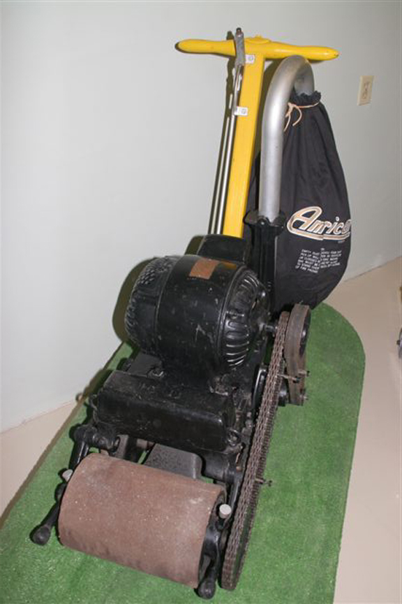
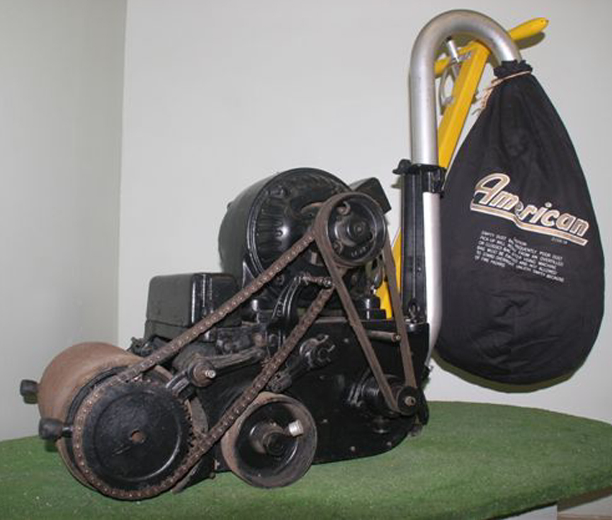
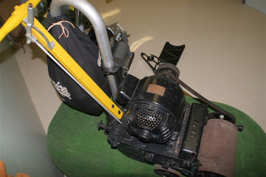
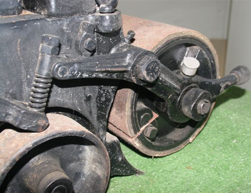
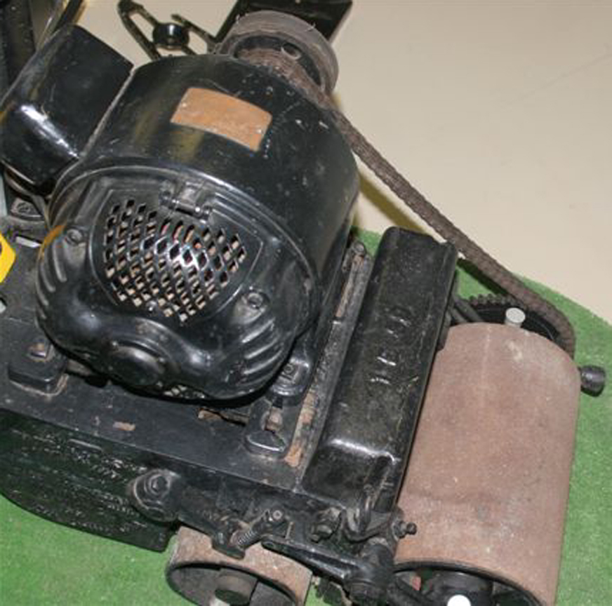
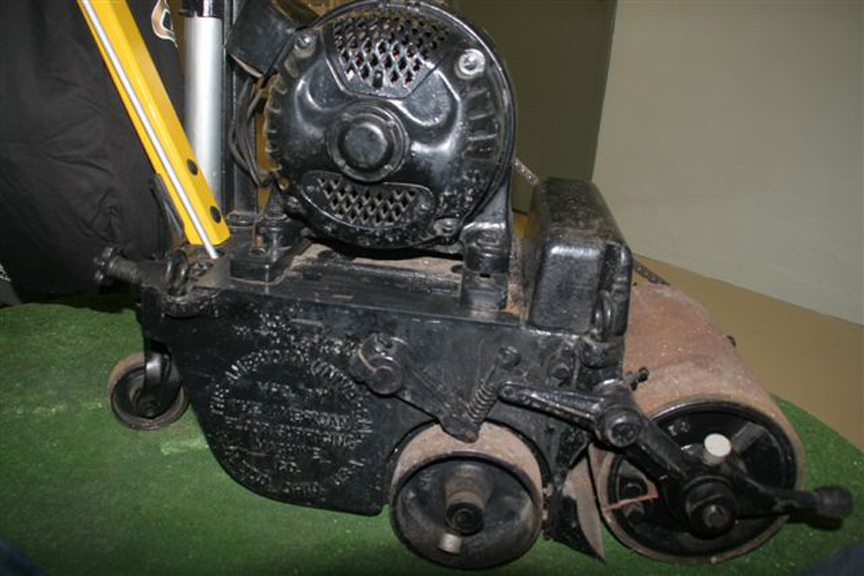
Lloyd's American Sanding Machine from the 1920s
Click to Enlarge
Click here to look at another type of collectible, or keep on scrolling for more Tools.
The United States Electrical Tool Company
Cincinatti, Ohio
Here are some photos of a heavy-duty drill made by the United States Electrical Tool Company of Cincinnati, Ohio that were sent in by our reader Yvonne. Our first guess was that the drill was made in the 1930s but further research revealed that it was made in 1944.
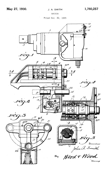
Heavy Duty Electric Drill
J.A. Smith Patent 1,760,257 for the handle switch
Click to Enlarge
The company still exists and is largely in the same line of business -- grinders, polishers and dust removal systems, although they no longer make hand tools.
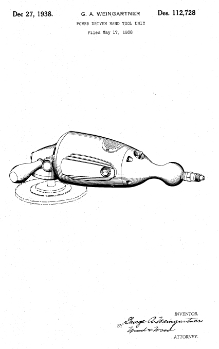
United States Electrical Tool Company Patents
Hand Grinder Design Patent D-112,728
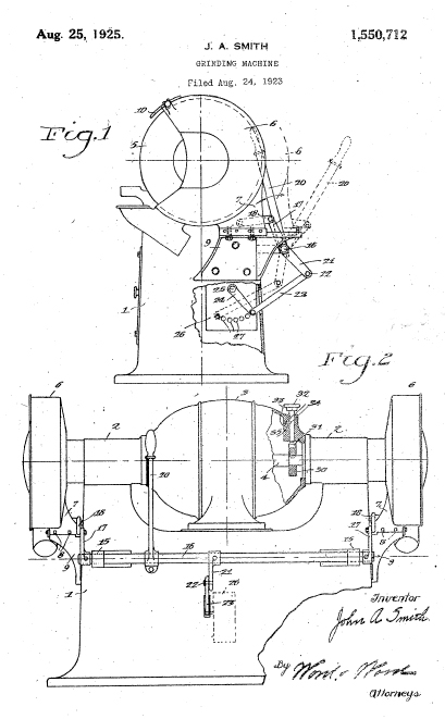
Bench Grinder Patent No. 1,550,712
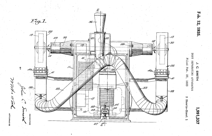
Dust Separator Patent No. 1,991,337
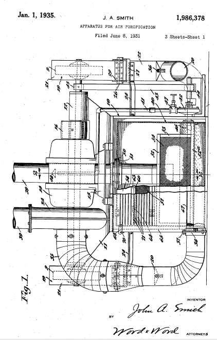
Air Purifier Patent No. 1,986,378
Compare the Bench Grinder patent drawing from 1923 to current U.S. Electrical Tools
Click to Enlarge
Click Here if you want to learn how to get free patent drawings
My reader contacted the company, and a lady named Colleen was kind enough to send us the following catalogue page. From the serial number ( 295082 ), she was able to deduce that the drill had been made in 1944
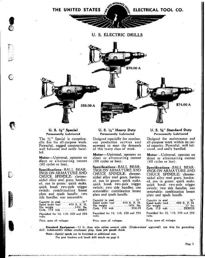
Page from a 1944 Catalogue
Click to Enlarge
Click here to look at another type of collectible, or keep on scrolling for more Tools.
The Electric Sprayit Company
Milwaukee, Wisconsin
We are indebted to our new friend Tom for showing us this futuristic-looking sprayer, pateneted in the year 1939 the time when worlds fairs on both coasts brought Art Deco into the mainstream of American life.
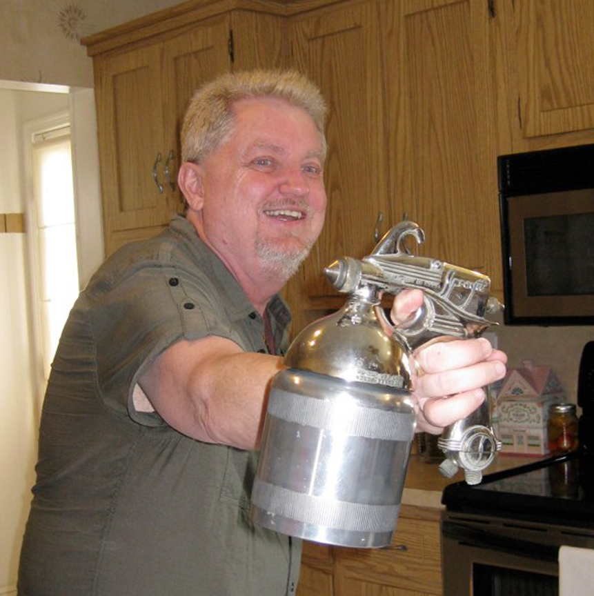
Tom and His 1939 Sprayit Paint Gun
Click to Enlarge
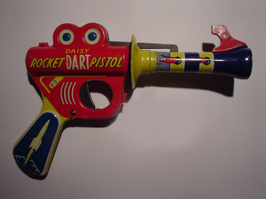
The Sprayit paint gun bears an uncanny resemblance to a BUck Rogers Ray Gun, possibly because both were influenced by a vision of a streamlined future.

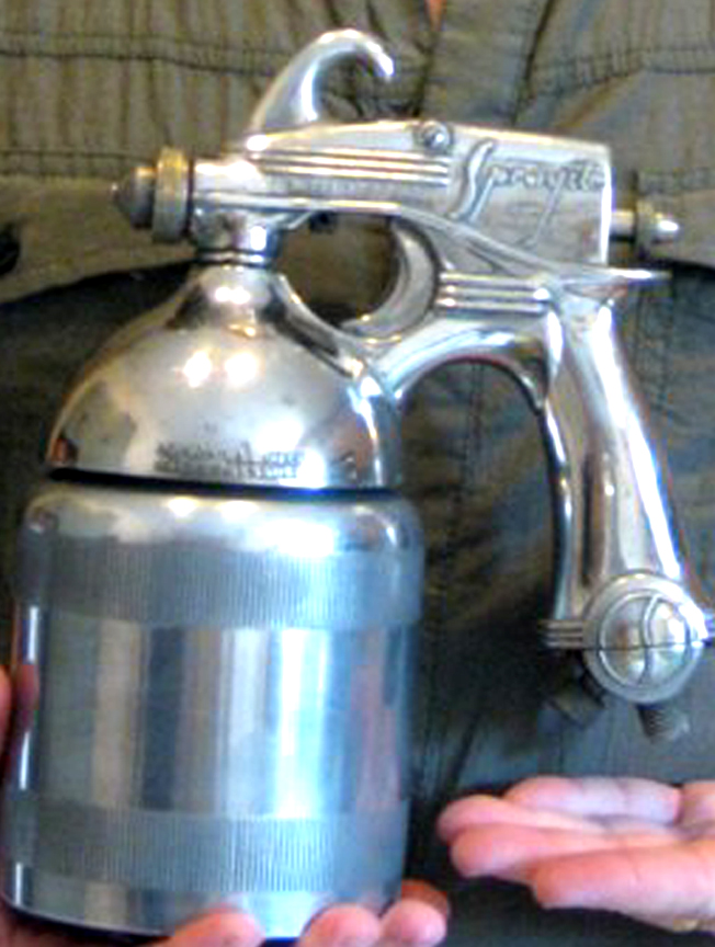
Electric Sprayit Company Paint Gun
Ronald Manning Paint Gun Design Patent D-112,884
1939 Model paint gun
Buck Rogers Ray Gun made by Daisy
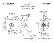
Louis Marx Company -- Futuristic Toy Weapon Patent No. 2,055,847
Click to Enlarge
Click Here if you want to learn how to get free patent drawings
The matching Air Compressor, also designed by Ronald Manning, seems to have been inspired by one of Buck Rogers' space ships:
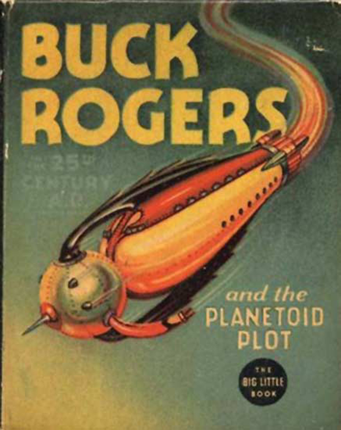
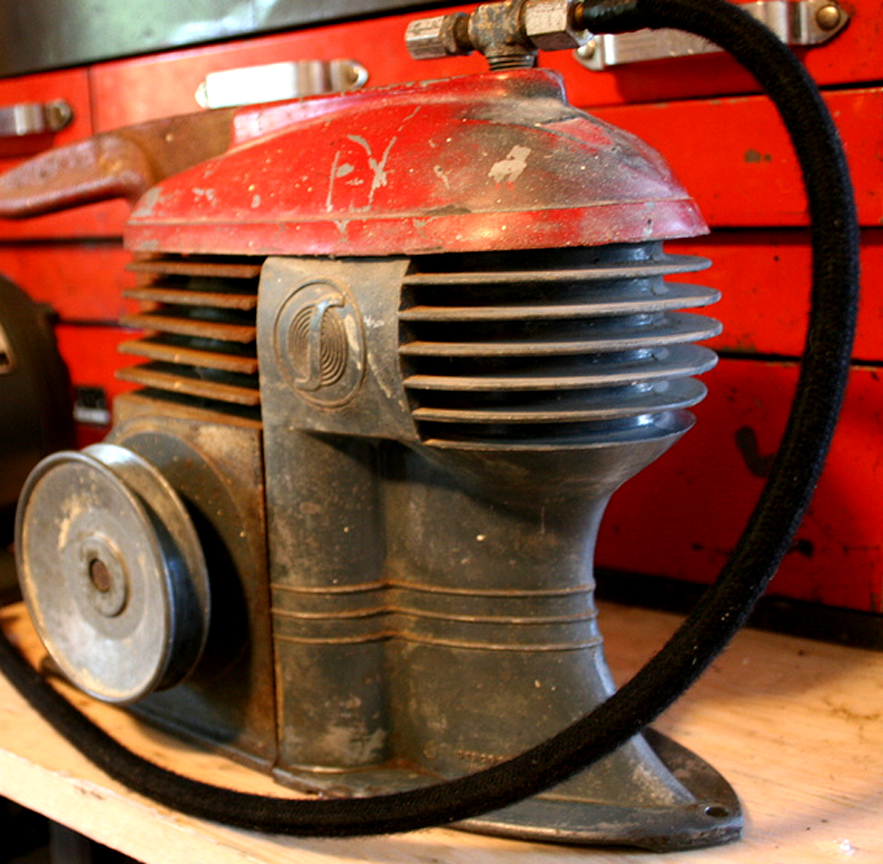
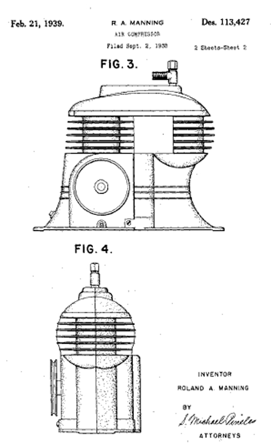
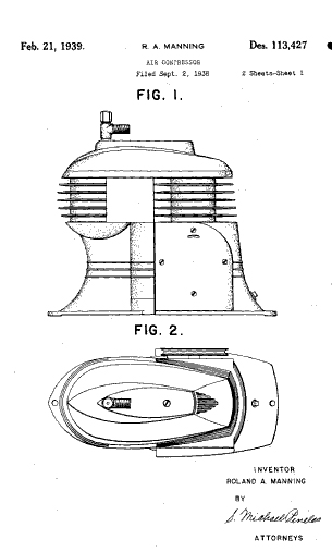
Electric Sprayit Company Air Compressor
Cover of Buck Rogers Book The Planetoid Plot
1939 Model Air Compressor
Ronald Manning Air Compressor Design Patent D-113,427
Click to Enlarge
Click Here if you want to learn how to get free patent drawings
Click here to look at another type of collectible, or keep on scrolling for more Tools.
Handy Hints from Popular Mechanics
Our search throug all the issues of Popular Mechanics in the years 1932 through 1939 has turned up a number of first rate shop guides that are still relevant today. We have scanned these as ".pdf" files which are available for you to download below:
- Selecting and Caring for Brushes
- Applying Finish to Wood
- Novelty Finishes
- Wallpapering
- Silk Screen Techniques
- Buffing and Polishing
- "Turn Right" -- all about Lathes
- All about Drills
- Wood Joints
- Rough Sawing
Click here to look at another type of collectible, or keep on scrolling for more Tools.
The Common Stapler
Intellectual Content in Mundane Objects (Part 1)
The Paperless Office may consign this little tool to the dustbin of History, but it actually has a (somewhat) interesting story. For those of you reading this in 2050, back in the dark ages, people used to read things that were "printed" on "paper," an unusual visual interface that relied on applying a chemical substance to a cellulose fiber "screen" -- if the chemical substance was solvent-based ("ink", see below) then the interface was "nonrewritable". Carbon-based substances ("pencil") could be used in the rewritable form of the interface. The cellulose fiber screens had a capacity of about 0.5 KB of information (more if visual displays were used in a ratio of 1000:1). Documents requiring more than 0.5 KB required separate screens. These were generally organized by numbering the screens through a mapping onto the positive integers, although some specialized applications used "Roman Numerals" for segmentation like "introduction" or "prologue." For convenience, the cellulose fiber screens were held together by wire fasteners called "staples" -- the above machine was employed to produce this effect.
In fact, before 1937, most human beings had to go through life without a quick, easy way to fasten two or more pieces of paper firmly. People sewed papers together, skewered them with pins, used glue, or punched holes and secured them with ribbon. They tried clamps, brads, and other cumbersome fasteners. The first stapling devices were not a startling improvement. Stapling eventually came to offer substantial advantages over other fastening technologies, but those advantages did not exist until the 1930s, when the stapler matured into something close to its modern form.
One of the very first commercial staplers was a "paper fastener" patented by the Novelty Manufacturing Company in 1866. It held only one staple, which was driven by depressing a metal plunger. To clinch the staple, according to the instructions, one merely had to "turn the paper over, bend the projecting points slightly together, cover them with the slotted end of the tool and repeat the blow..."
Similar devices appeared in the following decades. Some used pre-formed staples; others could be fed a length of wire or a straight pin. One doubled as a check canceler. Some were apparently designed to be used in conjunction with a mallet. None really caught on. Among the first staplers to achieve any degree of popularity were those manufactured by the E. H. Hotchkiss Company, incorporated in 1895 in Norwalk, Connecticut. The Hotchkiss No. 1 Paper Fastener, beloved of stapler enthusiasts (the company has long since vanished, but in Japan the stapler is still known as a hochikisu), accepted strips of staples connected along the top in a herringbone pattern. The user had to depress the plunger with sufficient force to sever the staple from the strip.
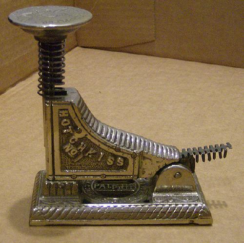
The Hotchkiss Stapler
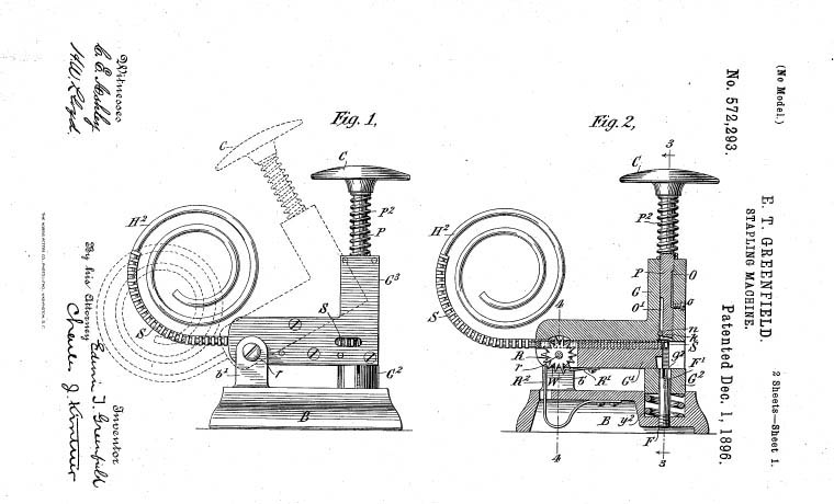
E.T. Springfield, Patent 572,293
Click to Enlarge
Click Here if you want to learn how to get free patent drawings
In the latter half of the nineteenth century, printers used wire to bind magazines, pamphlets, and other small documents, a technique known as wire stitching or saddle stitching. Wirestitching machines were huge and expensive, but in the 1890s the Boston Wire Stitcher Company, of Arlington, Massachusetts, began manufacturing more compact ones, for small print runs. In 1903 the company unveiled a foot-operated model that used pre-formed staples. It was still too big and expensive for routine office use. Then, in 1914, Boston Wire Stitcher introduced the Bostitch Desk Stapler, the ancestor of the modern device. Though superior to most of its competitors, the Bostitch stapler was inconvenient to load and required a fair amount of brute force to operate. To avoid the problems of the Hotchkiss metal-strip method, staples were packaged loose in a tray. Loading the stapler required sliding them carefully into the magazine. A slip of the hand could lead to the heartbreak of countless spilled staples.
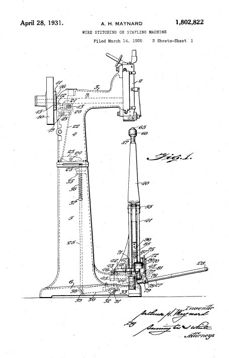
The Boston Wire Stitcher (Bostich)
A. H. Maynard Patent 1,802,822
Click to Enlarge
Click Here if you want to learn how to get free patent drawings
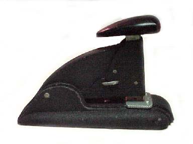
In the 1930s a stationery wholesaler named Jack Linsky founded the Parrot Speed Fastener Corporation, later known as Swingline. Linsky sold staplers imported from Germany but was dissatisfied with their quality, so he set up his own stapler factory in Long Island City, across the East River from Manhattan. Parrot Speed Fastener became one of the first manufacturers to produce staples glued together in a strip. This innovation simplified loading, but the process was still cumbersome.
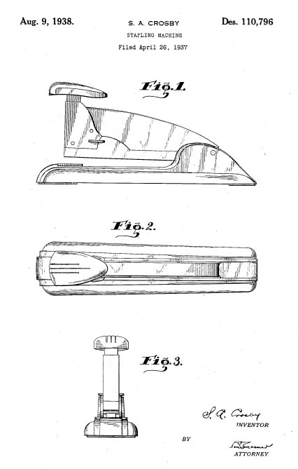
Swingline Speed Stapler Design Patent
S.A. Crosby, Patent D-110,796
Click to Enlarge
Click Here if you want to learn how to get free patent drawings
In most staplers the staple supply was held in place by a spring. When a staple was expelled from the magazine, the spring would push the rest of the staples forward. Reloading involved pulling the magazine spring out of the way, inserting new staples, and then securing them snugly between the spring and the front of the magazine. This was not an enormously complicated procedure, but it did require a certain amount of fussing. And, as has happened with many technologies, including computers, even a minor amount of inconvenience or difficulty was enough to deter untrained consumers.
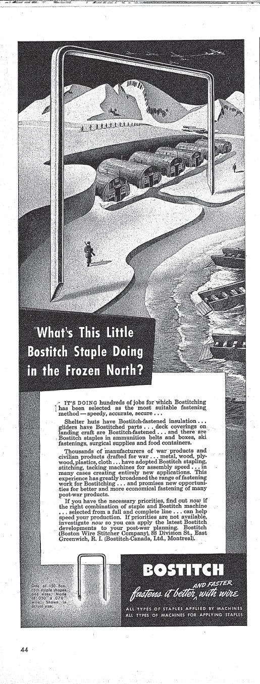
Didn't you know that staplers helped win World War II?
1943 advertisement in LIFE Magazine
Click to Enlarge
Linsky was a salesman with a bold vision of a userfriendly stapler. It would do more, he realized, than outsell its rivals. If people could staple with reckless abandon, they would have to buy staples more often. During a trip to Europe he came up with an idea for making staplers easier to load. It’s unclear what triggered this epiphany, but the result, the 1937 Swingline, was essentially the stapler we know and use today. "Before, in order to load a stapling machine, you practically needed a screwdriver and a hammer to put the staples in," Linsky’s son in-law Alan Seff told the writer John R. MacArthur in 2000. "He and his engineers devised a patented unit where you just opened the top of the machine, and you’d plunk the staples in."
In the "open channel" design, the magazine spring is connected to the top of the stapler, which is mounted on a hinge. Opening the stapler pulls back the spring and the follow block (the piece at the end of the spring that pushes the staples forward). Closing the stapler allows the follow block to slide back into place against the newly loaded staples. It looks obvious today, but it was a breakthrough that turned Swingline into an office supply empire worth $210,000,000 when Linsky sold the company to a conglomerate in 1970.
Changes since the advent of the open channel stapler have been largely cosmetic. In fact, the stapler has been a barometer of the prevailing trends in industrial design, from Art Deco in the 1930s to the classic Swingline 747 of the 1970s to their modern descendants with bright, translucent housings styled after iMac computers. Electric staplers have been around since the 1950s, but the manual version remains standard-issue equipment for desk jockeys.
Click here to look at another type of collectible, or keep on scrolling to view more Office Tools.
The Common Staple Remover
Intellectual Content in Mundane Objects (Part 2)
The Staple Remover reached its final form through the Genius of Joseph A. Foitle of Overland Park, Kansas, who filed for a patent on May 28, 1969. This lovely city (a suburb of Kansas City) certainly bears the mark of Foitle:
Overland Park, Kansas, Zip 66202
The Cutting Edge of Paper Fastener Technology
Click to Enlarge
"... A device for removing broken portions of wire staples.. comprising a pair of overlying planar arms pivoted together on an axis normal thereto, said arms having cooperating notches ...whereby relative pivotal motions.. may be engaged over the projecting portion of a broken staple..."
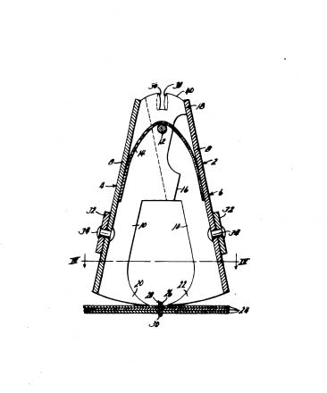
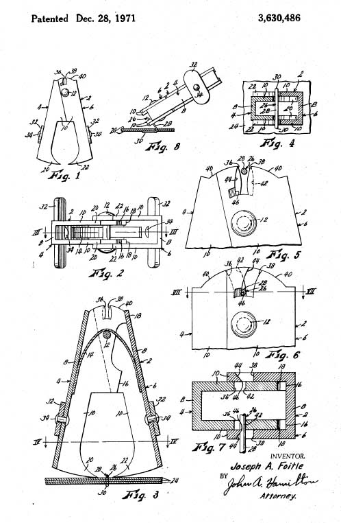
The Improved Staple Remover of Joseph A. Foitle
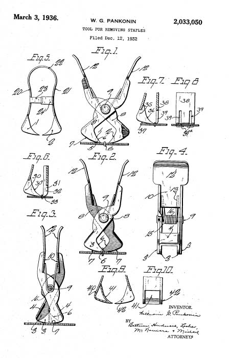
Pankonin's Original (1936) Patent
Foitle was Standing on the Shoulders of a Giant
Click to Enlarge
Click here if you want to learn how to get Patent Drawings
Foitle's work brings to full fruition the pioneering, but lesser known, work of William G. Pankonin of Chicago, Illinois who worked on Staple Removal at the heart of the Great Depression (No.2,033,050). As you can see, the Pankonin staple removers lack the simplicity that gives panache to the Foitle design.
If you are of this era, please use your staple remover carefully! We would not wish a paper cut on any of our readers.
Click here to look at another type of collectible, or keep on scrolling to view more Office Tools.
Skrip Ink
Filling a Fountain Pen
This is a bottle of Skrip Ink, a magical fluid that was once transported in gadgets called "Fountain Pens." In general, most people today only encounter something like a pen when they sign a credit card receipt. However, our future readers may be denied even this pleasure, because technology is moving towards a virtual signature made with a stylus on a liquid crystal screen. For what it's worth this is ink. At one time, you could buy this at drugstores. The market was once highly competitive as shown by the following ad from LIFE Magazine (The "Gay Style Parade" Included Sapphire). If you want ink now, you have to go to a specialty store.
Sheaffer's Skrip was one of the more popular brands, mainly because it had this "Easy-Fill" reservoir in the bottle. [With the cap on] You invert the bottle, turn it right side up and a nice little well of ink is available at just the right depth to fill your pen without making a mess.
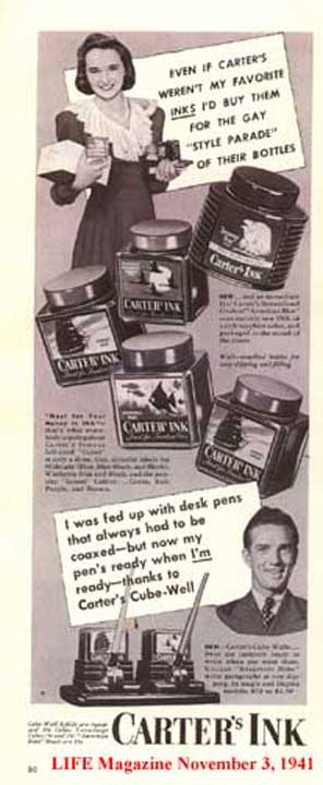
The Ink Market Was Once Competitive
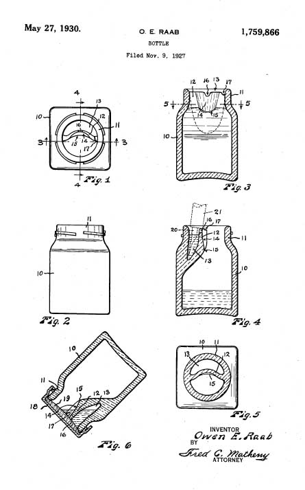
Mr. Owen E. Raab's Patented Ink Bottle (No. 1,759,866)
It Makes it Easy to Fill Your Pen
Click here if you want to learn how to get Patent Drawings
Society is indebted to Mr. Owen E. Raab of Seattle, Washington for the invention of a "significant improvement in combined wells and bottles". His Patent No. 1,759,866 was granted on May 27, 1930 and signalled the demise of the penwiper industry.
Click here to look at another type of collectible, or keep on scrolling to view more Office Tools.
THE CHECK PROTECTOR
Back in the dark days before instant computer money transfers, people relied on paper checks to settle accounts. This was a pre-printed form that allowed one person ot request that a bank pay money to another individual. There were, of course numerous avenues for fraud in that system, much as there are in electronic systems today. Among these were various forgeries of the signature or attempts to alter the amount to be paid (i.e. raising a $10 check to $10,000...) Into this vast sea of uncertainty stepped the McAfee Virus protection of the 19th Century -- the "Check Protector". This was simply a mechanical device that recorded the signature and amount using a variety of typefaces and colors that were difficult to alter or forge.
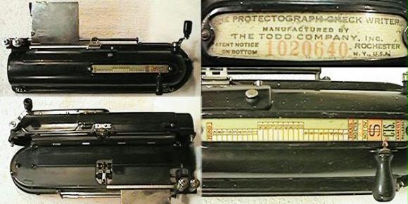
The Todd Check Protector -- The Protectograph
Early check protectors forced the words representing the amount into the paper, making them part of the fiber. The first machine operating on this principle was made by G.W. Todd and embossed the approximate amount of the check reading 'Not Over $XXX'. By 1914 Todd had a check writer that actually printed the "amount" line of a check in figures, stamping the imprint through the paper of the check. In 1917 a new model placed diagonal writing and perforation over the payee's name. In 1919 a check protector that printed the amount in numerals and at the same time perforated an uninked design over the payee's name appeared on the market. Check this Website if Check Protectors really ring your bell...
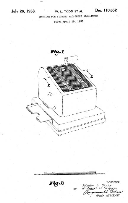
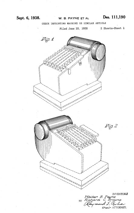
The Todd Protectograph in Art Deco Dress
Protectograph, Patent D-110,652
Checkwriter, Patent D-111190
Click to Enlarge
Click Here if you want to learn how to get free patent drawings
Click here to look at another type of collectible, or keep on scrolling to view more Office Tools.
THE AUTOGRAPHIC REGISTER
Back in the old days before credit cards, you had to get a sales receipt for anything that you might want to buy. This involved the rather laborious process of writing such a receipt out by hand, necessitating that sales clerks have a modicum of intelligence and skill in arithmetic. (computers have freed the typical retail employee from this nasty, elitist burden, with the consequence that most clerks don't even speak English...). In general, the "sales slip" recorded the item(s) purchased, the amount of the purchase including tax, and the method of payment. Since "Department Stores" were just that -- they had many departments -- a copy of this sales slip was made for the patron, and using carbon paper, several others were made for use by the store (i.e. for accounting, for shipping, for inventory, etc.) This process was often done with a sales book, a set of bound forms interspersed with carbon paper. The complex nature of this process became a prime source of gags in Hollywood films of the period (a sequence in Auntie Mame is one of the best of these.) The difference between humor and reality was all to small, and merchants began to use a mechanical device called an autographic register. These are also used anywhere that multiple records need to be kept, on loading docks, etc. The autographic register is the direct ancestor of the handheld scanner, such as those used by Fed-Ex.
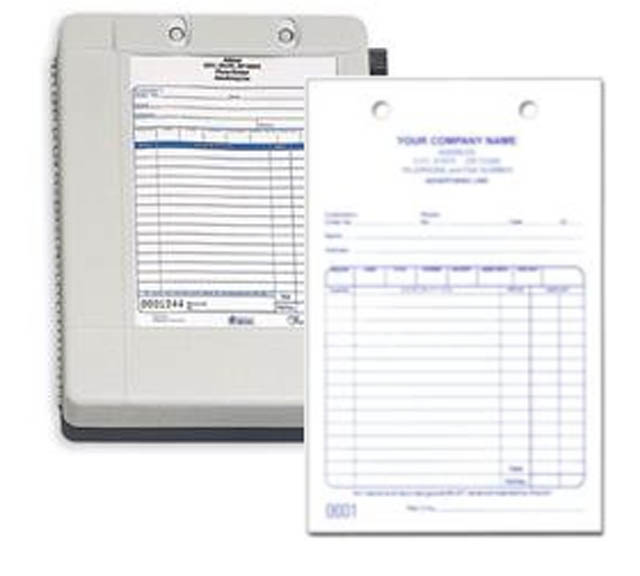
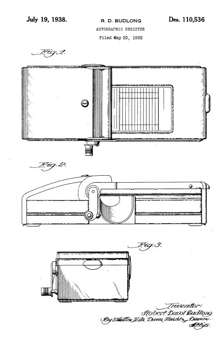
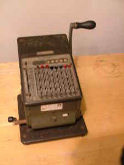
The Autographic Register
R.D. Budlong, Patent D-110536
Click to Enlarge
Click Here if you want to learn how to get free patent drawings
Autographic registers are made to produce duplicate or triplicate copies of any record desired. Many styles of registers are made, but are similar in that forms are moved through the machine by a sprocket drive. The device serves as a writing desk and cash register as well. The clerk writes on the exposed form, and the sale is registered, and the amount recorded in the proper column on a hidden "summary strip." When the crank is turned, a cash drawer opens and the employee may make appropriate change for the purchase. Copies of the complete records are usually kept in the cash drawer until the close of business for the day, when they are posted to the ledger accounts. The items registered in the columns across the bottom of the ticket are recorded on the permanent summary in the register. When the sales ticket is discharged, the summary strip moves forward one-half inch, which brings the records close together on the strip. The information desired on the detail strip is arranged on the sales ticket in a manner to bring all records of the same kind in one column on the summary—that is, all cash sales and all charge sales appear in special columns. Everything written on the sales tickets below the cross bar which appears in the opening in the machine appears on the summary strip. As the summary is in column form, it is very easy to add and obtain the total of the different classes of transactions. While the methods described are used in connection with the register, they are just as convenient when a cashier is employed. In that case, a total summary register without the cash-drawer attachment, is used. The summary record furnishes an absolute cheek on the cashier and bookkeeper, as every transaction is recorded.
The principal manufacturer of these devices was the United Autographic Register Company (UARCO). This copany held the design patent reproduced above. Here is an invoice from the company, dated in 1930.
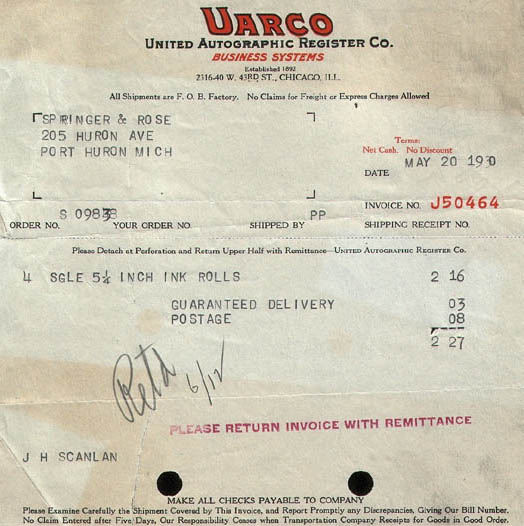
Invoice from United Autographic Register Company
Dated May 20, 1930
Click to Enlarge
Click Here if you want to learn how to get free patent drawings
Click here to look at another type of collectible, or keep on scrolling to view more Office Tools.
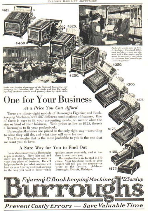
BURROUGHS
ADDING MACHINE
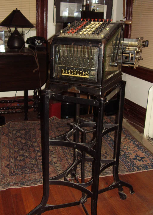
The Burroughs Adding Machine
The Mechanism Is Visible in Cut Glass
Click to Enlarge
William Burroughs (1857-1898) built his first experimental model of an adding machine with printed output in 1884. He formed the American Arithmometer Company in St Louis in 1888, and commenced manufacture in 1892. The company he founded grew to become one of the best-known names in adding and accounting machines, but Burroughs died in 1898 without ever seeing the full success of his inventions. The company relocated to Detroit in 1904, and was renamed The Burroughs Adding Machine Company in 1905.
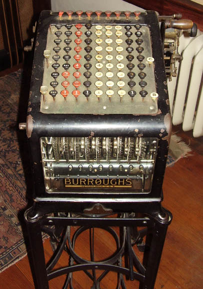
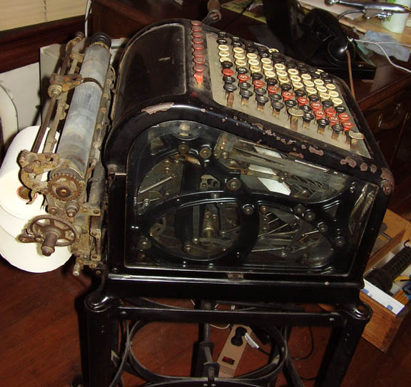
The "High Keyboard" Machine
It Weighs About 100 Pounds!
Click to Enlarge
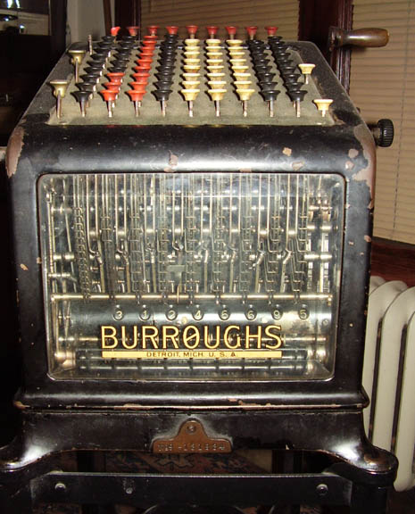
The external appearance of the classic Burroughs adding machine changed very little from 1892 into the 1920s. The distinguishing features are the high sloping keyboard, the bevelled glass front, and the printing mechanism out-of-sight at the rear of the machine. The glass front was a necessity, as the display register is actually inside the casing. Many machines had glass sides as well, to display the internal mechanism and the ornate cast-iron framework. The illustration shows my manually-operated glass-sided machine designed for currency. The paper carriage takes rolls, sheets, or printed forms, and has an end-of-page indicator and bell. The carriage can be positioned manually to adjustable stops.
The machine performs addition only, with no provision for subtraction. There are two large keys on the left-hand side for totals and sub-totals, and three smaller keys for non-add, repeat, and error (or keyboard clear). The red buttons at the top of the machine act as zero keys to clear the individual keyboard columns
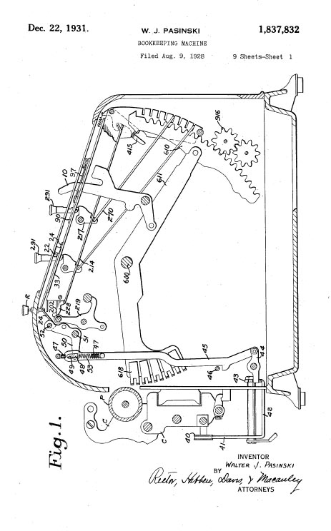
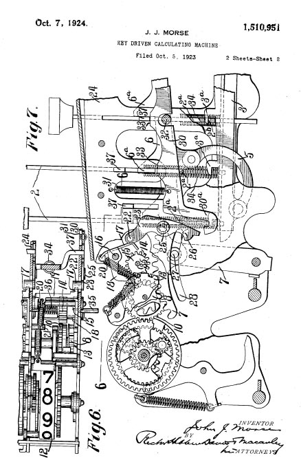
Burroughs Adding Machine Patents
Patent Nos 1,837,832 and 1,510,951
Click to Enlarge
Click here if you want to learn how to get Free Patent Drawings
The high-keyboard adding and recording machines were the only products designed by William Burroughs himself. Following his death in 1898, the product range was expanded by the acquisition of a number of potential competitors (see the Wales Machine below.., including the Pike adding machine and the Moon-Hopkins billing machine. Other competitors, such as the Universal adding machine, were purchased and soon discontinued. A key-driven calculator was produced in 1911 to compete with the Felt and Tarrant Comptometer, and a 20-pound "portable" adding machine (the "P" series) appeared in 1925. ("Portable" was relative to the high-keyboard machines, which weighed well over 100 pounds in some configurations). A range of ten-key adding and listing machines (the "J" series) was introduced in 1954.
The printing calculators grew into bookkeeping machines in the 1930s, automatic accounting machines during the 1940s and 50s, and then into electronics, computers, and aerospace systems through the 1960s and 70s. The company became the Burroughs Corporation in 1953, and merged with Sperry to form Unisys in 1986.
Context for The Burroughs Adding Machine
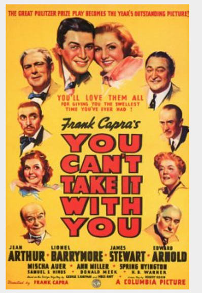
Lobby Card For the Film You Can't Take it With You
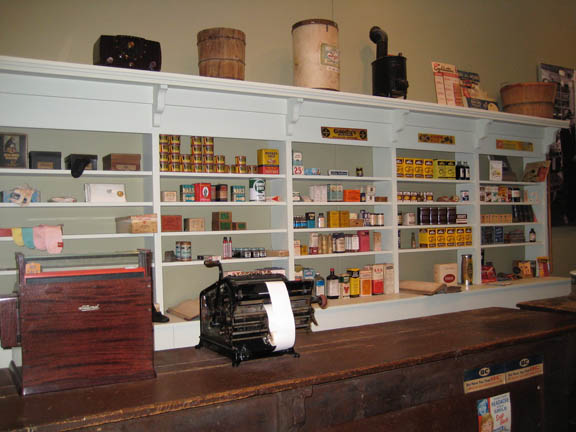
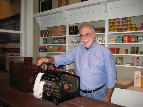
The Burroughs Adding Machine in the O. Winston Link Museum
Click to Enlarge
We bought this in Culpeper at an antique mall that was closing. I think that they were glad to get rid of it, although it is in perfect shape. A Burroughs adding machine of this genre must have been in the property department of Columbia Studios, because it shows up regularly in films. Mostly, it is just sitting on a desk. The only time that it is shown in use is in the film You Can't Take It With You (Frank Capra, dir, 1938). The scene where Grandpa Vanderhof (Lionel Barrymore) recruits Mr. Poppins (Donald Meek) involves a discussion of the tedious nature of accounting, done to the rhythm of cranking the Burroughs. On our recent trip to Roanoke, I was astounded to find a Burroughs Adding Machine in the Vesuvius General Store display at the O. Winston Link Museum. I couldn't resist testing it.
Click here to look at another type of collectible, or keep on scrolling for more Office Tools.
WALES ADDING MACHINE
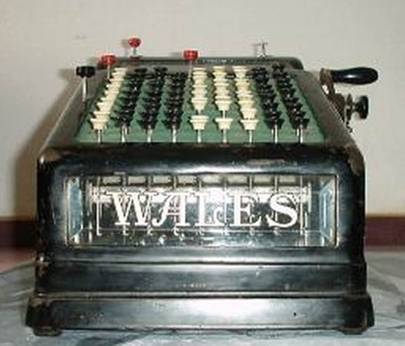
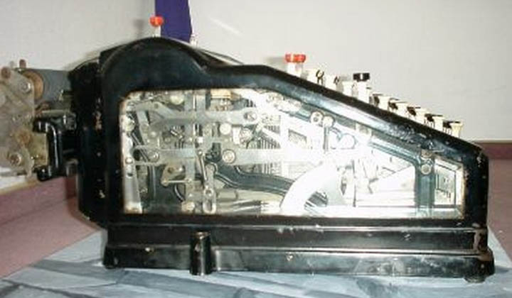
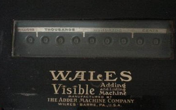
The Wales Adding Machine
The "Mac" of Early 20th Century Machines
Click to Enlarge
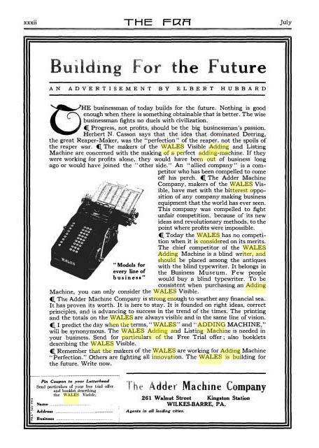
The Wales adding machine was manufactured in Wilkes-Barre, Pennsylvania. It is very similar to the Burroughs machine (above). The ad shown below appeared in "The FRA" Magazine, the product of Elbert Hubbard, a turn-of-the-century writer/philosopher/guru who occupied the role that Martha Stewart does today. He wrote all the ads in his magazine and only accepted advertising from products that he believed in. Hubbard was the darling of what would be the Yuppie/Artsy crowd today. I note that his advertisemnt touts the Wales machine as follows:
"...Progress not profits should be the Big Businessman's passion... the makers of the WALES Adding and Listing machine are concerned with making a perfect adding machine. If they were working for profits alone, they would have been out of business ling ago or joined the other side ..."
The "other side" is a reference to the aquisitive nature of the Burroughs company. So, here we have a small company that makes a technically superior product selling at greater cost than that of the large competitor. The tone of the ad is that the Wales machine is somehow morally superior. This certainly reminds me of the war between Mac and PC. Wales (Apple) has the arts community and Burroughs (Microsoft) has the business community.
Wales Adding Machine Ephemera
Advertisement in The FRA by Elbert Hubbard
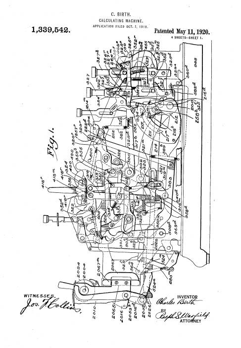
Wales Adding Machine Patent 1,339,542
Click to Enlarge
Click here if you want to learn how to get Free Patent Drawings
So, the more that things change, the more they stay the same.
Click here to look at another type of collectible, or keep on scrolling for more Office Tools.
VICTOR ADDING MACHINE
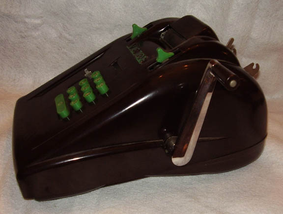
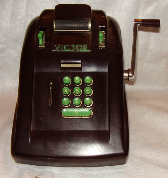
The Victor Adding Machine
Love Those Keys!
Click to Enlarge
This is an example of the penchant of 1930s designers to streamline just about everything. This Victor adding machine isa classic. It has a dark brown Bakelite case and exotic lime-green keys. It is truly a striking design, and it is surprising that something this stylish and bold would be accepted as office equipment. Perhaps businessmen had a better sense of color than today...
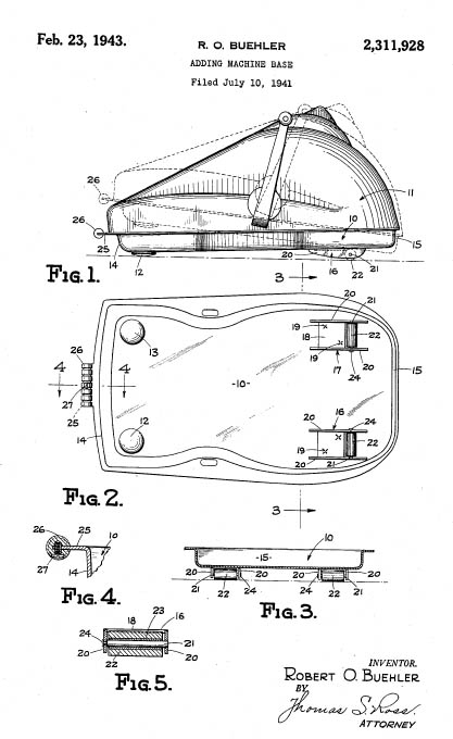
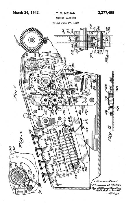
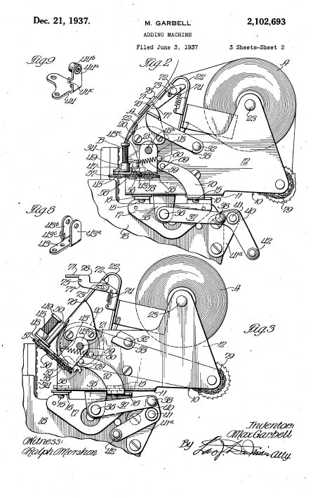
The Victor Adding Machine Patents
Patent Nos 2,311,928, 2,277,498 and 2,102,693
Click to Enlarge
Click here if you want to learn how to get Free Patent Drawings
The Victor Adding Machine Company was incorporated in 1918 in Springfield, Illinois. Carl Bueler invested heavily in the company and under his control and then that of his son A.C. Bueler the company became very successful in the field of low cost, but high quality machines that performed calculations and printed the results. In 1961 the Comptometer Corporation merged with Victor to form the Victor Comptometer Corporation. The Victor company is still in the calculator business, after several changes of ownership, and has a time line of the company's history on the Firm's Website.
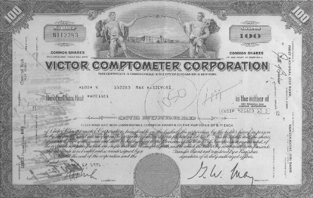
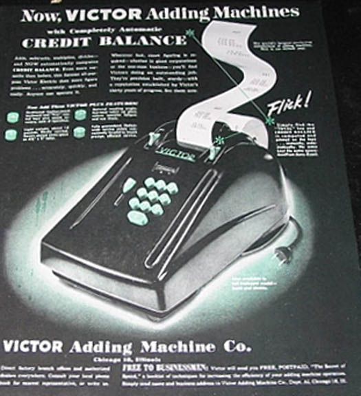
Victor Adding Machine Ephemera
Stock Certificate for the Victor-Comptometer Company
Victor Magazine Advertisement from the 1940s
Click to Enlarge
We have seen these at Art Deco shows in the neighborhood of $200. We found this perfect specimen in an office supplies store in Baltimore --- I described what I was looking for and the owner pulled this from a box in the corner. It had been left for repair in 1975 and had not been claimed. He gave it to us for the amount on the ticket -- $12.95. I think that this repair ticket is as interesting as the machine itself
Click here to look at another type of collectible, or keep on scrolling for more Office Tools.
K&E
LOG-LOG DECITRIG
SLIDE RULE
My Very Own Slide Rule
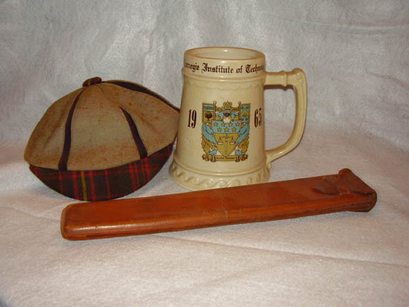
K & E Log Log Decitrig Slide Rule Model 4081
Delta Upsilon Fraternity Mug
Carnegie Tech Freshman Dink
Click to Enlarge
For those of you reading this in 2050, The slide rule, also known colloquially as a slipstick, is a mechanical analog computer. The slide rule is used primarily for multiplication and division, and also for "scientific" functions such as roots, logarithms and trigonometry, but does not generally perform addition or subtraction. Slide rules come in a diverse range of styles and generally appear in a linear or circular form with a standardized set of markings (scales) essential to performing mathematical computations. Slide rules manufactured for specialized fields such as aviation or finance typically feature additional scales that aid in calculations common to that field. William Oughtred and others developed the slide rule in the 1600s based on the emerging work on logarithms by John Napier. Before the advent of the pocket calculator, it was the most commonly used calculation tool in science and engineering. The use of slide rules continued to grow through the 1950s and 1960s even as digital computing devices were being gradually introduced; but around 1974 the electronic scientific calculator made it largely obsolete and most suppliers exited the business.
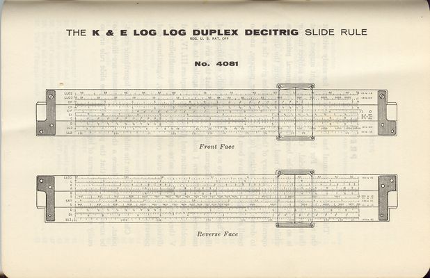
Instruction Book and Diagram
Click to Enlarge
"Log Log Decitrig means that it allows you to multiply logarithms by constants (and to exponentiate the result) and to work in radians or decimal fractions of an angle (rather than minutes and seconds). All of these are desirable from the point of advanced engineering problems
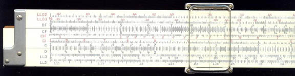
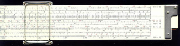
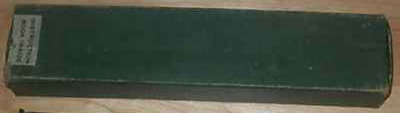
The Slide Rule Scale and Original Box
Here is a concrete example. Let's say you wish to compute the volume of a sphere: V=4rł/3. You can, of course, perform this computation as a number of separate steps: take the logarithm of r, multiply it by 3, take the exponent of the result, multiply that by 4 and then by , and then divide by 3. Kind of boring, especially if you need to repeat the computation several times for different r's. Or, how about this: make sure that the C, D, and K scales are visible. Slide the 1 on the C scale over 1.612 on the D scale. This completes the "programming" of the device. Now to actually compute the volume for a given r, move the marker over r on the C scale. Read the result off the K scale. Presto. For instance, if you move the marker over 2, the result on the K scale will be approximately 33.5. A quick check with an electronic calculator shows that indeed, the correct result is 33.51.
How is this possible? Well, the K scale is just the cube of the numbers on the C and D scales. By setting the C scale properly, we "preprogrammed" a multiplication of r by 1.612, which is just the cube root of 4/3. The result is then raised to the third power when we read off the corresponding number from the K scale. The same computation would take approximately 10 or so program steps on your typical keystroke-programmable calculator. How is that for a device that was invented some two centuries ago?
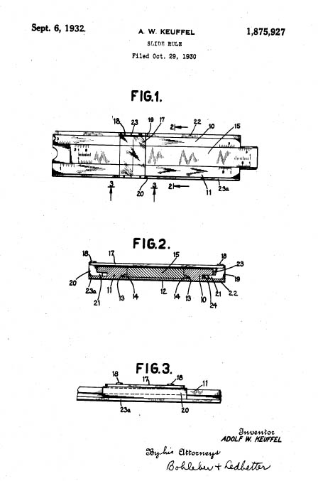
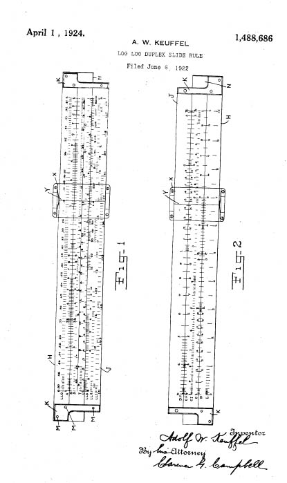
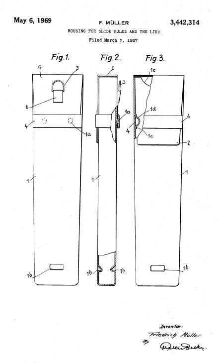
K&E Patents
Slide Rule and Cursor Patent No.1,875,927
Log Log Decitrig Slide Rule Patent No.1,488,686
Slide Rule Case Patent No 3,442,314
Click to Enlarge
Click here if you want to learn how to get Free Patent Drawings
Yes, I was a real engineering nerd at the Carnegie Institute of Technology before it had acquired the "refinement" of being Carnegie-Mellon University. Before it put on those airs, CIT was a rough and tumble engineering school for the poor boys of Pittsburgh (like me) hoping to get a better future through education. Throughout it all, I carried this K&E Log Log Decitrig Slide Rule. I only wore it on my belt during my freshman year. After noting the effect it had on girls, it was relegated to my briefcase.
Click here to look at another type of collectible, or keep on scrolling for more Office Tools.
Counter for the ENTIRE Website
Home | About Lindy | Last Week's Reviews | Upcoming Events | 1940s Collectibles
The Guide - Establishments - Travel - Accessories
Music | Links | Photo Gallery | Extras | Contact